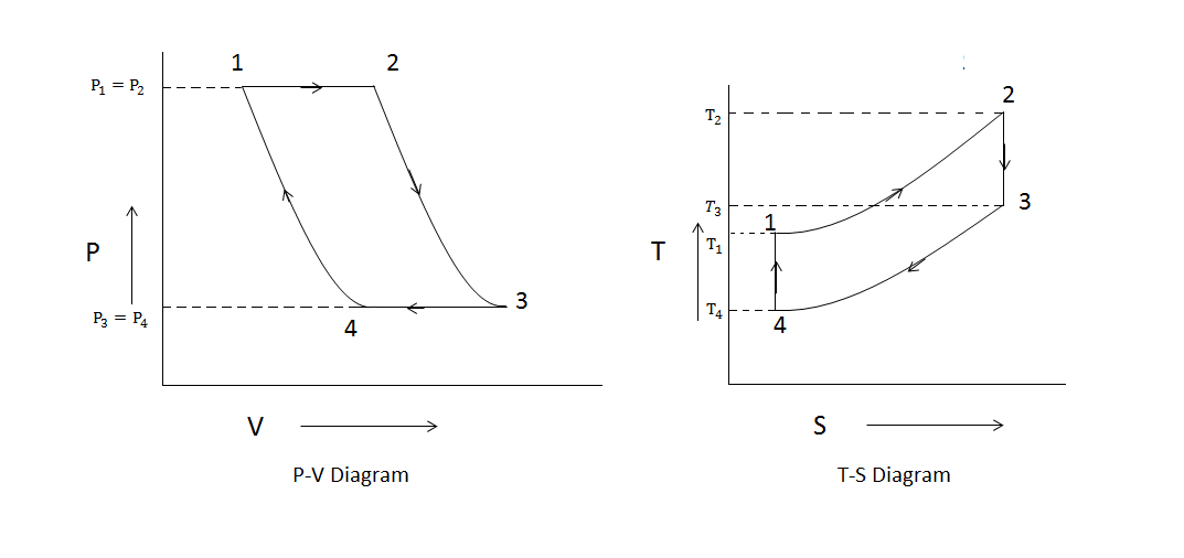
Turbine diagram gas cycle closed working pv various mechanical booster construction processes used P-v diagram and work – geogebra Representation breathing engines
PPT - MAE 4261: AIR-BREATHING ENGINES PowerPoint Presentation - ID:3206347
Phase changes Closed cycle gas turbine: construction, working, diagram Thermodynamics bartleby pv
P-v diagram problems and solutions
P-v diagramPhase temperature physics pressure critical temperatures pv gas curve isotherm changes relationship between diagram volume change liquid ideal vapor constant Pv piston followed moleIsothermal process constant diagrams p1 v1 data.
Refrigeration: p v diagrams for refrigerationWork diagram done geogebra cycle positive Refrigeration adiabatic pv thermodynamics grc thermodynamic irreversible conditioningIsothermal process on p-v, t-v, and p.


Phase Changes | Physics

Isothermal process on p-V, T-V, and p

P-V Diagram | bartleby

Closed Cycle Gas Turbine: Construction, Working, diagram - Mechanical

Refrigeration: P V Diagrams For Refrigeration

P-V Diagram and Work – GeoGebra
P-V Diagram Problems and Solutions
